
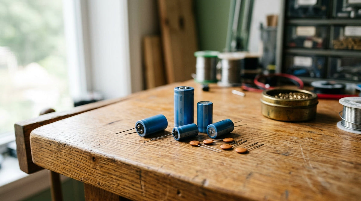
A resistor is easy to picture: it limits current. A capacitor is harder, because what it does depends on time. The short version is that a capacitor stores a small amount of electric charge and resists any sudden change in the voltage across it.
Inside
Two conducting plates sit close together, separated by an insulator. Apply a voltage and charge builds up on the plates. Remove the voltage and the charge stays until something gives it a path to flow away.
Because of the insulator, steady direct current cannot pass through a capacitor. A changing voltage can, in effect, because the plates keep charging and discharging.
Three jobs you will see constantly
- Smoothing. A capacitor across the supply acts as a tiny reservoir, filling in dips. That is why you see a small 0.1 µF capacitor beside the power pins of almost every chip.
- Timing. A capacitor charging through a resistor takes a predictable time. Multiply resistance by capacitance for the time constant: 10 kΩ × 100 µF = 1 second, the time to reach about 63 percent of the supply voltage.
- Coupling. A capacitor between two stages passes the audio signal and blocks the steady voltage underneath it.
Before you fit one
Capacitance is measured in farads, and practical values are in microfarads (µF), nanofarads (nF) and picofarads (pF). Electrolytic capacitors are polarised: the stripe marks the negative lead. Always choose a voltage rating comfortably above your supply.
If you want the fundamentals in one place, with hand-drawn diagrams, start with Getting Started in Electronics, or browse all four books.