
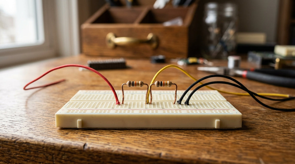
Put two resistors in series across a supply, and the voltage at the point where they meet is a fixed fraction of the supply. That is a voltage divider, and once you can spot one you will find it in nearly every schematic.
The formula
Call the resistor connected to the positive side R1 and the one connected to ground R2. The output, taken from the junction, is:
Vout = Vin × R2 ÷ (R1 + R2)
Two equal resistors halve the voltage: 9 volts in, 4.5 volts out. With R1 = 10 kΩ and R2 = 20 kΩ on a 5 volt supply, the output is 5 × 20 ÷ 30 = 3.33 volts.
What it is good for
- Reading sensors. Replace one resistor with a light-dependent resistor or a thermistor and the output voltage follows light or temperature.
- Setting a reference. A comparator needs a threshold to compare against, and a divider supplies it.
- Adjustable voltages. A potentiometer is simply a divider with a sliding junction.
What it is not good for
A divider is not a power supply. Anything you connect to the output sits in parallel with R2 and pulls the voltage down. The rule of thumb: the load should draw no more than about a tenth of the current flowing through the divider itself. To power something at a lower voltage, use a regulator.
If you want the fundamentals in one place, with hand-drawn diagrams, start with Getting Started in Electronics, or browse all four books.