
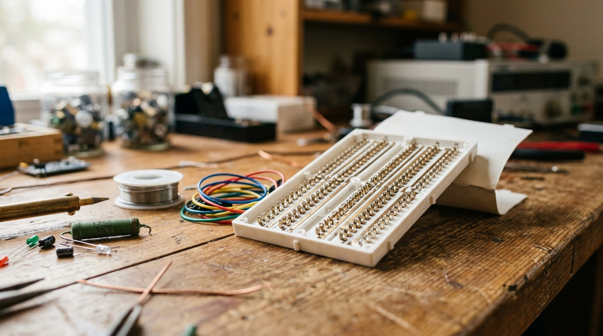
A solderless breadboard lets you build a circuit by pushing parts into holes. It only makes sense once you know which holes are connected to which, because nothing on the surface tells you.
The terminal strips
The main area is two blocks of holes separated by a channel down the middle. Within each block, the holes are joined in short rows of five running across the board. Push two leads into the same row of five and they are connected. Rows are not connected to their neighbours, and nothing crosses the channel.
That channel is spaced so a chip in a dual in-line package can straddle it, giving every pin its own row with four free holes beside it.
The power rails
Along each long edge are one or two lines of holes joined lengthwise, usually marked red and blue. Connect your battery here and you have positive and ground available along the whole board.
One catch: on many full-size boards the rails are broken in the middle. If half of your circuit is dead, check the rails with a multimeter and bridge the gap with a short wire.
Working habits
- Use solid 22 gauge wire. Stranded wire will not push in cleanly.
- Red for positive, black for ground, other colours for signals.
- Keep wires short and flat so you can see what you built.
- Keep currents small. Breadboard contacts are for signals and LEDs, not motors.
Count holes when you place a part. Being one row out is the most common breadboard mistake there is.
If you want the fundamentals in one place, with hand-drawn diagrams, start with Getting Started in Electronics, or browse all four books.